
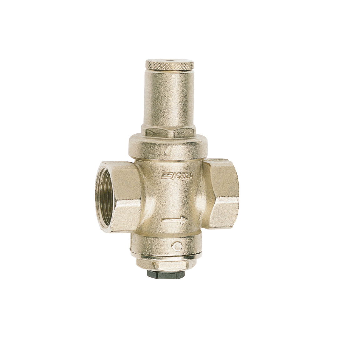
Female pressure reducer. 1/4” connection for manometer
Piston technology
Max.inlet pressure 16 bar
Adjustable outlet pressure from 1 bar to 4 bar (company setting 3 bar)
Max. working temperature 90°C.
ICMA pressure regulators are devices that
reduce and stabilize the incoming pressure
from the public network. Installed on the
private water network, they allow a correct use
on domestic systems, reducing malfunctions
due to external pressure which is generally
high and variable.
Characterized by reduced overall dimensions
and noisiness, the 247 – 248 models are used
in small users, mainly in apartments and as a
protection device for the boiler.
OPERATING PRINCIPLE
The gearbox operation is based on the balance of two
opposing forces that develop inside it.
The spring produces a thrust towards the opening of the
fluid passage section as opposed to the spring which
produces a thrust towards closing
SUPPLY OPERATING
When opening a water utility, the valve (1) moves
downwards, opening the passage of water, this is due to
the force exerted by the spring which, in these
conditions, becomes prevalent with respect to the force
exerted by the water.
Increasing the demand for water causes an increase in
the passage of the fluid through the passage section
caused by the decrease in pressure to which the valve is
normally subjected. The opening of several users causes
a pressure drop (Δp) downstream and a consequent
increase in the flow rate
When the loads are closed, the downstream pressure
increases until it reaches the value set during the
calibration phase.
INSTALLATION
For a correct installation open all the supply valves to facilitate the cleaning of
the system and expel the air possibly remaining in the pipes.
The gearbox can be installed in any position. We recommend the installation of
shut-off valves upstream and downstream to facilitate any future maintenance
operations.
After closing the downstream shut-off valve it is possible to carry out the
calibration by unscrewing the plastic cap and acting on the screw placed on the
top of the screw (Fig.2) Screw in a proper size screw clockwise to increase the
calibration pressure and counter-clockwise to decrease it.
Through a pressure gauge it is possible to display the set value.
Models 247 – 248 have a factory setting of 3 bar.
Body: Brass CW617N UNI EN 12165
nickel-plated
Internal components: Brass CW617N UNI EN 12165
Seals: NBR
Spring: AISI 302 stainless steel
Closing caps: NYLON PA 66
Connections
Measure: ½ “- ¾”
Pressure gauge connection: ¼ “F
Performance
Max upstream pressure: 16 bar
Downstream pressure calibration range: 1 ÷ 4 bar
Factory setting: 3 bar
Max working temperature: 90 ° C
Working fluids: water
| Size | Code |
| 1/2″ | 91247AD06 |
| 3/4″ | 91247AE06 |


