Thermostatic valves are used to regulate and cut-off the flow of the heat transfer fluid that circulates inside air-conditioning
system terminals (radiators, fan coils, etc.).
Thermostat control devices are used in combination with the thermostatic valves to auto-matically regulate ambient temperature
wherever they are installed, keeping the temperature at a preset value. This avoids the needless wasting of heat and provides a
considerable saving of energy.
ICMA thermostat control devices can be installed on all thermostatic valves of this line to convert heating systems with manual operating mode to
automatic operating mode.
To install the thermostat control device, simply replace the thermostatic valve knob with an ICMA thermostat control device. This is done with a few
easy operations. These are described in detail in the paragraph “Thermostat Control Device Installation and Regulation”.
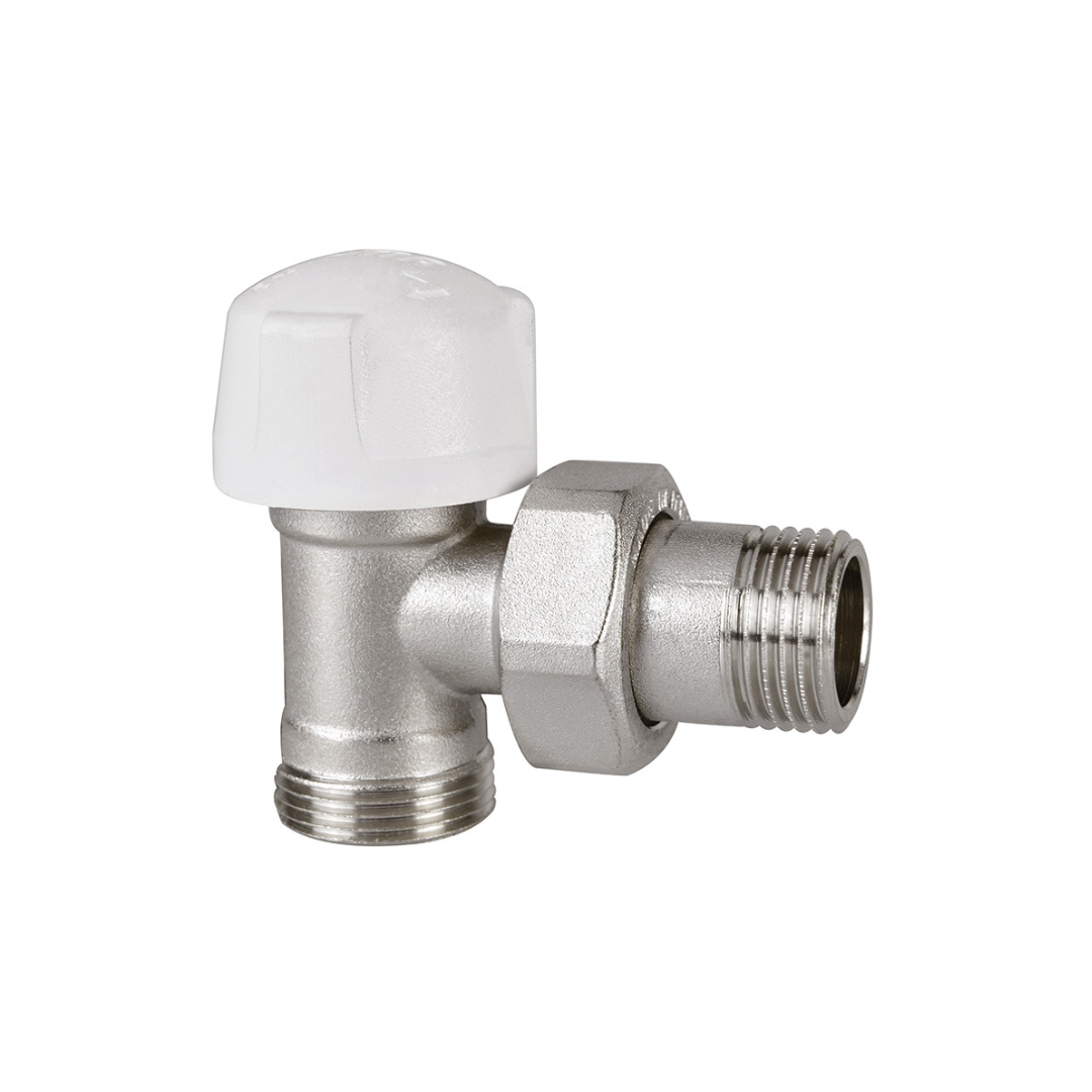
The valves come in “straight” and “angled” versions so that they can be connected to two different types of pipes, at the side of the heating system:
−The valves with GAS thread (side of heating system) are designed for connection to a steel pipe.
−The valves with standard ICMA thread (side of heating system) are designed for connection to a copper pipe, apolyethylene pipe and a multi-layer
polyethylene pipe, for which specific pipe fittings are provided.
Pressure loss can be detected by following the indications provided in the diagrams shown in the paragraph “Fluid Dynamic Characteristics”.
Install ICMA thermostatic valves on the heating system making sure to observe the direction of flow. The fluid must enter from the side on which the
valve is connected to the system and go out toward the heating body.
The following problems can occur if the valve is installed incorrectly:
-A noise similar to a continuous sound of heavy hammering is due to the passage of fluid through the valve in thewrong direction. This problem can
only be solved by inverting the valve with holder on radiators that have thisproblem, thus restoring the correct direction of flow of the fluid inside
the valve.
-A noise similar to a sound of heavy whistling during the succession of specified on and off times is due to an excessive flowinside the valve. This
problem can be solved by keeping the system pressure under control, and equipping the system withvariable rotation pumps along with differential
pressure regulators, or by making use of differential by-pass valves.
Performance
Fluids used: Water, glycol solutions
Max percentage of glycol: 50%
Max operating pressure: 10 Bar
Max differential pressure: 1 Bar (control dev. mounted)
Heat transfer fluid temperat: 5 ÷ 120°C
Valve obturator travel: 3,5 mm
Connection with control devices: 28 x 1,5
Materials
Body, cap and socket union: CW617N Brass – UNI 12165
(Nickel-plated)
Large screw: CW617N Brass – UNI 12164
Spring,obturator control rod: Stainless steel
Liquid sealings: Peroxy EPDM
Control knob: Nylon 6 – 30% Fiberglass
(White color)
| Size | Fitting thread | Code |
| 3/8″ | 24×1,5 | 82770AC06 |
| 1/2″ | 24×1,5 | 82770AD06 |
| 3/8″ | 1/2″ | 82772AC06 |
| 1/2″ | 1/2″ | 82772AD06 |